
Version Number | Date | Author(s)
|
| 3.0 | August, 2007 | Samer Abdulhadi |
| 2.0 | October, 2006 | Jennifer Horkoff, Eric Yu |
| 1.0 | August, 2006 | Gemma Grau |
Table of contents
- 1 Purpose
- 2 Using the Guidelines
- 3 Summary of i* Notation
- 4 i* Glossary and Guidelines
- 4.1 Strategic Dependency (SD) Model
- 4.1.1 Actors
- 4.1.2 Actor Association Links
- 4.1.2.1 Is-part-of (Part) Association
- 4.1.2.2 ISA Association
- 4.1.2.3 Plays Association
- 4.1.2.4 Covers Relationship
- 4.1.2.5 Occupies Relationship
- 4.1.2.6 INS Relationship
- 4.1.2.7 Guideline (Beginner,Concept) Use 'ISA' and "Is part of' Association Links only between actors of the same type. Discuss
- 4.1.3 Strategic Dependencies
- 4.1.3.1 Goal Dependency
- 4.1.3.2 Task Dependency
- 4.1.3.3 Resource Dependency
- 4.1.3.4 Softgoal Dependency
- 4.1.3.5 One-Side Dependency
- 4.1.3.6 Guideline (Intermediate,Concept & Evaluation) Use the Dependency link to indicate a Strategic Dependency relationship between two Actors Discuss
- 4.1.3.7 Guideline (Beginner,Notation) Use the “D” symbol notation to denote a Dependency Link. Do not use other symbols such as arrow heads, which can be confused with other types of links. Discuss
- 4.1.3.8 Guideline (Beginner,Concept) Do not use Dependency Links inside an Actor. Discuss
- 4.1.3.9 Guideline (Beginner,Concept) Ensure that both sides of a Dependency Link point in the same direction. Discuss
- 4.1.3.10 Guideline (Intermediate,Concept & Evaluation) Do not reuse Dependums in more than one Dependency Relation. Discuss
- 4.1.3.11 Guideline (Beginner,Concept) Do not use a Dependency Link between two actors without showing the Dependum. Discuss
- 4.1.3.12 Guideline (Beginner,Layout) Avoid or minimize drawing intersecting Links and overlapping Links with other Links and elements’ text. Discuss
- 4.1.3.13 Guideline (Beginner,Layout) Make both sides of a Dependency Link look like a single, continuous curve as it passes through the Dependum. Discuss
- 4.1.3.14 Guideline (Beginner,Layout) Sperad the connection points of Dependency Links out on an Actor. Discuss
- 4.1.3.15 Guideline (Beginner,Layout) Keep elements horizontal. Do not tilt or twist them. Discuss
- 4.1.4 Vulnerability
- 4.1.5 Strategic Dependency Example Model: Buyer Drive E-Commerce from Yu01
- 4.2 Strategic Rationale (SR) Model
- 4.2.1 Boundary / Actor Boundary
- 4.2.1.1 Guideline (Beginner,Layout) Avoid or minimize overlapping boundaries of Actors where possible. Discuss
- 4.2.1.2 Guideline (Beginner,Layout) Keep Dependency Links outside the boundaries of Actors to improve the readability of the models. Discuss
- 4.2.1.3 Guideline (Beginner,Layout) Use the conventional Actors’ boundaries (circles) unless other shapes such as rectangles can improve the overall layout. Discuss
- 4.2.2 Elements/Nodes
- 4.2.2.1 Goals (Hard Goals)
- 4.2.2.1.1 Guideline (Beginner,Concept) Use a Softgoal for quality criterion and use a (hard) goal for a sharply defined objective. Discuss
- 4.2.2.1.2 Guideline (Beginner,Concept) Do not confuse Softgoal with optional, less important Goals. The criticality, or importance, or priority of a goal is orthogonal to the distinction between a hard goal and a Softgoal. Discuss
- 4.2.2.1.3 Guideline (Beginner,Concept) To indicate that a Goal can be achieved by performing several sub-tasks, model the decomposition by introducing a Task. Discuss
- 4.2.2.1.4 Guideline (Beginner,Concept) Use multiple Means-End Links from Tasks to a Goal to indicate alternatives. Discuss
- 4.2.2.1.5 Guideline (Beginner,Concept) Don’t mix Goals and Tasks in the Means-Ends links. Discuss
- 4.2.2.1.6 Guideline (Beginner,Naming) Use precise language to name a Goal or a Task. Discuss
- 4.2.2.1.7 Guideline (Beginner,Concept) A Goal can only be decomposed using Means-Ends Links. Discuss
- 4.2.2.2 Softgoals
- 4.2.2.2.1 Guideline (Beginner,Concept) Do not confuse between a Softgoal and a Task. Discuss
- 4.2.2.2.2 Guideline (Beginner,Notation) Use the proper i* Softgoal notation. Discuss
- 4.2.2.2.3 Guideline (Intermediate,Concept & Evaluation) Softgoals and Goals should be decomposed. Discuss
- 4.2.2.3 Tasks
- 4.2.2.4 Resources
- 4.2.2.4.1 Guideline (Beginner,Concept) Use a Resource when the Actor asks for the provision of a clearly defined and concrete resource, which can be physical or information entity. Discuss
- 4.2.2.4.2 Guideline (Beginner,Concept) Model a human or system as a resource only if you want to ignore their goals and intentions. Discuss
- 4.2.2.5 Beliefs
- 4.2.2.6 Guideline (Beginner,Layout) Avoid overlapping elements inside or outside Actors. Discuss
- 4.2.2.7 Guideline (Beginner,Layout) Connect each Strategic Dependency Link in an SR model to the correct element within the actor. Discuss
- 4.2.2.8 Guideline (Beginner,Layout) Adopt or follow a consistent direction for the goal refinement/decomposition hierarchy as much as possible. Discuss
- 4.2.2.9 Guideline (Beginner,Layout) Do not draw SR model elements outside the boundaries of the corresponding actors. Discuss
- 4.2.2.10 Guideline (Beginner,Layout) Unconnected elements within an Actor is indicative of an incomplete model. Discuss
- 4.2.2.1 Goals (Hard Goals)
- 4.2.3 Means-Ends Links
- 4.2.4 Decomposition Links
- 4.2.4.1 Guideline (Beginner,Concept) Be consistent with the direction of the Task Decomposition Link between a Task and sub Task or Resource. Discuss
- 4.2.4.2 Guideline (Beginner,Concept) Be consistent with the direction of the Task Decomposition Link between a Task and a Softgoal. Discuss
- 4.2.4.3 Guideline (Beginner,Concept) Do not extend Decomposition Links beyond the boundaries of actors. Discuss
- 4.2.4.4 Guideline (Beginner,Concept) Don’t use the Task Decomposition Link or Means-End Link to refine Softgoals. Discuss
- 4.2.5 Contribution Links
- 4.2.5.1 Make
- 4.2.5.2 Some+
- 4.2.5.3 Help
- 4.2.5.4 Unknown
- 4.2.5.5 Break
- 4.2.5.6 Some-
- 4.2.5.7 Hurt
- 4.2.5.8 Or
- 4.2.5.9 And
- 4.2.5.10 Guideline (Beginner,Concept) Use Contribution Links from any element only to a Softgoal element. Discuss
- 4.2.5.11 Guideline (Beginner,Concept) Avoid introducing ad hoc or improvised link types. If you must, define their syntax and semantics as extensions to i*. Discuss
- 4.2.5.12 Guideline (Beginner,Concept) Use the OR Contribution Links to indicate alternatives for satisficing a Softgoal. Discuss
- 4.2.5.13 Guideline (Beginner,Concept) Don’t use Correlation or Contribution Links between actors. Discuss
- 4.2.5.14 Guideline (Beginner,Concept) Don’t use Correlation or Contribution Links from a Task to a Task. Discuss
- 4.2.6 Leaf Elements
- 4.2.7 Strategic Rationale Example Model: Buyer Drive E-Commerce from Yu01
- 4.2.8 Operationalizations and Refinement of Goals and Softgoals
- 4.2.8.1 Guideline (Beginner,Concept) Use Contribution Links to decompose or refine a broad softgoal or non-functional requirement (NFR) into smaller components. Discuss
- 4.2.8.2 Guideline (Beginner,Naming) To facilitate systematic refinement, use Type and Topic naming convention for Softgoals. Discuss
- 4.2.8.3 Guideline (Beginner,Naming) Where Softgoals are named according to the Type and Topic structure, be consistent in each Softgoal refinement step to refine either by Type or by Topic. Discuss
- 4.2.1 Boundary / Actor Boundary
- 4.3 Naming, Icons, and Colors
- 4.3.1 Guideline (Beginner,Naming) Avoid including non standard elements or notations in the model. Discuss
- 4.3.2 Guideline (Beginner,Naming) Be consistent when using colors in the models. Discuss
- 4.3.3 Guideline (Beginner,Naming) Use a suitable font size for the element name. Discuss
- 4.3.4 Guideline (Beginner,Naming) Select concise but informative phrases to name the elements. Discuss
- 4.3.5 Guideline (Beginner,Layout) Don’t extend the text of the name of the element beyond the element’s boarder. Discuss
- 4.3.6 Guideline (Beginner,Naming) Do not use Verbs in the names of Actors, Agents and Positions. Discuss
- 4.3.7 Guideline (Beginner,Naming) Use clear names without ambiguous and unknown abbreviations or acronyms. Discuss
- 4.4 Scaling
- 4.4.1 Guideline (Intermediate,Layout) Split a large and complex model into consistent pieces to facilitate easier presentation and rendering. Discuss
- 4.4.2 Guideline (Intermediate,Layout) Don't extract or zoom into a section of an Actor in a model without showing the incoming and outgoing dependencies with other Actors or parts of the model. Discuss
- 4.5 Level of complexity
- 4.6 Model Analysis
- 4.6.1 Ability
- 4.6.2 Workability
- 4.6.3 Viability
- 4.6.4 Believability
- 4.6.5 Evaluation and Propagation
- 4.6.5.1 Evaluation Procedure
- 4.6.5.1.1 Guideline (Intermediate,Evaluation) To achieve more reliable and accurate evaluation results, employ a systematic evaluation procedure instead of using a manual mental method to guess the answer for an analysis question. Discuss
- 4.6.5.1.2 Guideline (Intermediate,Evaluation) In order to fully account the effects of all elements in the model, follow the evaluation procedure and steps in order. Discuss
- 4.6.5.1.3 Evaluation Step 1: decide what analysis question you are asking the model
- 4.6.5.1.4 Evaluation Step 2: Give initial Labels to “leaf nodes or elements” based on the question that you have decided to apply in Step 1.
- 4.6.5.1.5 Evaluation Step 3: Propagate Label Values
- 4.6.5.1.6 Evaluation Step 4: Interpret the Results
- 4.6.5.1.7 Step 5: Repeat steps 1 to 4 for each analysis question
- 4.6.5.1 Evaluation Procedure
- 4.7 Methodology
- 4.7.1 Early and Late Requirements
- 4.7.1.1 Guideline (Beginner,Methodology) Model the As-Is state of the knowledge domain and the current system status (if exists) without the presence of the new system To-Be introduced. Discuss
- 4.7.1.2 Guideline (Beginner,Methodology) Model the To-Be state of the knowledge domain under analysis including the new To-Be system. Discuss
- 4.7.1.3 Guideline (Beginner,Methodology) Start the modeling with the SD model to capture the stakeholders and their associated strategic Dependency dependencies and interactions. Discuss
- 4.7.1.4 Guideline (Beginner,Methodology) Employ SR models to expand on the SD models and add the intentionality and rational dimension to the analysis. Discuss
- 4.7.2 Progressive Elaboration
- 4.7.3 Guideline (Beginner,Methodology & Layout) Use the leaf-level tasks as the system requirements, not the high level functional goals and non-functional softgoals. Discuss
- 4.7.1 Early and Late Requirements
- 4.1 Strategic Dependency (SD) Model
- 5 Acknowledgments
- 6 References
1 Purpose
1.1 Education
The i* Guide is intended to be both an introduction to i* for new users and a reference guide for experienced users. It is constituted of basic i* notation and a glossary and provides relatively elaborated material on the usage of the i* framework and notation through introducing guidelines that are associated with discussions and illustrations. These Guidelines, which touch on some of the fundamental concepts of i* Framework, are intended to, among other desirable modeling characteristics, improve the readability, understandability, usability, and feasibility of i* models and enhance the overall consistency and effectiveness of the i* modeling process. Therefore, the net positive effect is to reduce variation in practice among users of i* modeling framework. Furthermore, the i* Guide refers the readers to original sources where more advanced, detailed, or thorough material and discussions can be found.1.2 Collaboration
As this guide is intended to be part of the i* collaborative wiki we encourage feedback and collaboration in terms of suggesting alternative i* syntax and semantics, including extensions to the Framework. However, in order to keep the Guide brief and easily understandable, we suggest collecting i* adaptations, expansions, and further examples in separate document(s), namely the istarSyntaxVariations page. If enough variations of i* usage are collected, this can facilitate interesting and useful comparisons.Moreover, and to facilitate this collaboration process, i* wiki will host two versions of the i* Guide: A stable version and an open version. The open version is accessible to all registered i* wiki users to comment and provide suggestions on individual guidelines. Therefore, it is highly appreciated and valued that i* community utilizes this open version as a basis to develop and enhance the i* Guide further. In effect, you can think of the open version as a prototype that invokes and generates further input toward the achievement of a better artifact. This link connects you to the individual wiki pages of the guidelines. Once connected, you will see a wiki page containing a list of Level and Type guidelines' categories (defined in the next Section 2, "Using the Guidelines") that lead you to the individual guidelines' pages. For example, if you click on Beginner under Level, you will see a list of all the guidelines categorized under Beginner Level. To access the page of any guideline in the list, just click on the guideline and the guideline page will open. You can use this guideline page for comments and discussions.
2 Using the Guidelines
Each guideline is annotated with a set of attributes of the form (Level, Type), where Level is: Beginner, Intermediate, or Advanced, and Type is: Concept, Naming, Notation, Layout, Methodology, or Evaluation.If a guideline is given more than one Category attribute, this means this guideline probably spans more than one Category. The objective of explicitly annotating the guidelines with these attributes is to help the users of the i* Guide to browse through or retrieve the guidelines based on any dimension of these attributes. This annotation also gives i* concerned researchers an idea about the current distribution and coverage of the guidelines over the spectrum of the annotated attributes.
The following is an explanation of each of the terms pertaining to Level and Category attributes:
Guidelines' Level attribute:
Level |
Description |
|---|---|
| Beginner | This level assumes that the modeler is a new user of i* modeling framework and has not been exposed to it previously |
| Intermediate | This level assumes that the modeler has been exposed to and used i* modeling framework to some extent and passed the level of violating fundamental i* guidelines |
| Advanced | This level is for modelers who acquired substantial knowledge about using and applying i* |
Guidelines' Type attribute:
Type |
Description |
|---|---|
| Concept | deals with the arrangement and organization of i* models and the way the contents of the models appear and are placed. It also covers issues related to modeling space and complexity |
| Naming | deals with how the actors, links, and elements are named. It also covers issues related to using colors and other non-conventional icons |
| Notation | deals with the proper selection and use of i* notation such as elements, actors, and links |
| Layout | deals with the arrangement and organization of i* models and the way the contents of the models appear and are placed. It also covers issues related to modeling space and complexity |
| Methodology | deals with the procedural choices or approaches that can help in attaining an overall systematic modeling process. |
| Evaluation | deals with using i* models to evaluate the satisfaction or denial of Actors’ intentional elements and strategic dependencies. Violating Evaluation guidelines could lead to incorrect or weak reasoning about the rational behind the satisfaction or denial of Actors’ intentional elements and strategic dependencies |
Also, the Guide presents both i* Glossary and the related Guidelines in section 4 to better organize the Guide and help the reader relate between the presented glossary and the associated guidelines more effectively and efficiently. The glossary provides the definitions for i* notation, vocabulary, and modeling language. The guidelines proceed after the glossary to provide recommendations, discussions, illustrations on the use of the i* modeling language. Therefore, in order to maximize the understandability and the return from using the Guide, it is recommended that the new i* users get acquainted first with the glossary and fundamental definitions of i* before proceeding to the guidelines and their associated discussions.
3 Summary of i* Notation
This section provides only the graphical notation of i* syntax. An explanation of each notation can be found in the i* Glossary and Guidelines Section. Note that as i* models can be created by a variety of software tools, there can be small variations in notation appearance, mainly pertaining to color and line size.Actors


Actor Associations
Elements


Links

Contribution Links
Strategic Dependencies
Dependency Strengths
SR Decomposition Links
SR Means-End Links
Contributions
4 i* Glossary and Guidelines
4.1 Strategic Dependency (SD) Model
Set of nodes and links where each node represents an actor and each link between two actors indicates that one actor depends on the other for something in order that the former may attain some goal. The SD model is used to express the network of intentional, strategic relationships among actors. SD diagrams depict the strategic dependencies between Actors, but do not depict the internal rational behind these dependencies.
4.1.1 Actors
Active entities that carries out actions to achieve goals by exercising its know-how. We use the term actor to refer generically to any unit to which intentional dependencies can be ascribed. Agents, roles and positions are sub-units of a complex social actor, each of which is an actor in a more specialized sense.
4.1.1.1 Role
Abstract characterization of the behavior of a social actor within some specialized context or domain of endeavor. Its characteristics are easily transferable to other social actors. The dependencies associated with a role apply regardless of the agent who plays the role.
4.1.1.2 Agent
Actor with concrete, physical manifestations, such as a human individual. We use the term agent instead of person for generality, so that it can be used to refer to human as well as artificial (hardware/software agents). An agent has dependencies that apply regardless of what roles he/she/it happens to be playing. These characteristics are typically not easily transferable to other individuals, e.g. its skills and experiences, and its physical limitations.
4.1.1.3 Position
Intermediate abstraction that can be used between a role and an agent. It is a set of roles typically played by one agent (e.g., assigned jointly to that one agent). We say that an agent occupies a position. A position is said to cover a role. A position is abstract and an amalgamation of roles. A position can be ascribed to a human or non-human, even though the later case is rare.
4.1.1.4 Guideline (Beginner,Concept) Use Agents/Roles instead of actors when the distinction is easily made. Discuss
Discussion: Actors are the general type, whereas, agents and roles are more specific. Therefore, it would be more accurate and not superfluous to model Actors as Agents or Roles when the distinction is clear between them. Some trade offs between using the general Actor notation as opposed to the specialized Actor notation are discussed in Section 4.5.1 “Agents, Roles, and Positions”.
4.1.1.5 Guideline (Beginner,Concept) Do not include an Actor within another Actor. Discuss
Discussion: Actors are active and autonomous entities that should be modeled separately. "Sub-system" in the illustration can be modeled
as actors that have Dependency Links with the main system and/or other actors. They can also be modeled with Association Links such as “is-part-of” and “ISA”, to the higher-level system.
4.1.2 Actor Association Links
The relationships between actors are described by graphical association links between actors.
4.1.2.1 Is-part-of (Part) Association
Roles, positions, and agents can each have subparts. Aggregate actors are not compositional with respect to intentionality. Each actor, regardless of whether it has parts, or is part of a larger whole, is taken to be intentional. There can be intentional dependencies between the whole and its parts, e.g., a dependency by the hole on its parts to maintain unity.

4.1.2.2 ISA Association
The is_a association represents a generalization, with an actor being a specialized case of another actor. Both ISA and Is-part-of can be applied between any two instances of the same type of actor.

4.1.2.3 Plays Association
The plays association is used between an agent and a role, with an agent playing a role. The identity of the agent who plays a role should have no effect on the responsibilities of that role, and similarly, aspects of an agent should be unaffected by the roles it plays.

4.1.2.4 Covers Relationship
The association link covers is used to describe the relationship between a position and the roles that it covers.

4.1.2.5 Occupies Relationship
The occupies link is used to show that an agent occupies a role, meaning that it plays all of the roles that are covered by the position.

4.1.2.6 INS Relationship
The ins association, representing instantiation, is used to represent a specific instance of a more general entity. An agent is an instantiation of another agent.

4.1.2.7 Guideline (Beginner,Concept) Use 'ISA' and "Is part of' Association Links only between actors of the same type. Discuss
Discussion: Role, Agent, and Position are autonomous social actors of different types, which characterize different levels of abstraction. This means that a Role, for example, can be part of another Role, but cannot be part of an Agent or Position. This is true also for Agent and Position. As explained in Guideline 4.1.1.4, a Role, however, can be associated with an Agent or Position using the Plays and Covers Association Links respectively. An Agent can be associated with a Position using the Occupies Association Link. Refer to Section 4.1.1 “Actors” and Section 4.1.2 “Actor Association Links” for definitions of various types of actors and association links.
Figure 1 depicts correct scenarios, which are true also for Agent, and Position. Figure 2 depicts incurrent or wrong scenarios that involve Roles, Agents, and Positions. Figure 3 depict scenarios that are allowed in incomplete (in progress) models as the available information to the modeler about the type (Role, Agent, or Position) of the general ‘Actor’ is not yet known. Once the information becomes available, the correct actor type should be used.
Figure 1 Correct scenarios of using Association Links
Figure 2 Incorrect scenarios that involve Roles, Agents, and Positions
Figure 3 Scenarios that are allowed in incomplete (in progress) models
4.1.3 Strategic Dependencies
DependeeActor who is depended upon on a dependency relationship.
Depender
The depending actor on a dependency relationship.
Dependum
Element around which a dependency relationship centers.
We distinguish among four types of dependencies, based on the type of the dependum: Resource dependency, Task dependency, Goal dependency, Softgoal dependency.
4.1.3.1 Goal Dependency
In a goal dependency, the depender depends on the dependee to bring about a certain state of affairs in the world. The dependum is expressed as an assertion statement. The dependee is free to, and is expected to, make whatever decisions are necessary to achieve the goal (namely, the dependum). The depender does not care how the dependee goes about achieving the goal.
4.1.3.2 Task Dependency
In a task dependency, the depender depends on the dependee to carry out an activity. The dependum names a task which specifies how the task is to be performed, but not why. The depender has already made decisions about how the task is to be performed. Note that a task description in i* is not meant to be a complete specification of the steps required to execute the task. It is a constraint imposed by the depender on the dependee. The dependee still has freedom of action within these constraints.
4.1.3.3 Resource Dependency
In a resource dependency, the depender depends on the dependee for the availability of an entity (physical or informational). By establishing this dependency, the depender gains the ability to use this entity as a resource. A resource is the finished product of some deliberation-action process. In a resource dependency, it is assumed that there are no open issues to be addressed or decisions to be made about the provision or achievement of the Resource entity.
4.1.3.4 Softgoal Dependency
In a softgoal dependency, a depender depends on the dependee to perform some task that meets a softgoal. A softgoal is similar to a goal except that the criteria of success are not sharply defined a priori. The meaning of the softgoal is elaborated in terms of the methods that are chosen in the course of pursuing the goal. The depender decides what constitutes satisfactory attainment of the goal, but does so with the benefit of the dependee’s know how.Based on all the concepts presented in Section 1.3.1.3 “Strategic Dependencies”, the modeler has the choice of using a Task, Resource, Goal, or Softgoal Dependency Link between actors in a model depending on the context of the design. Each case has different purpose and interpretation. For example, using a Task Dependency Link between two actors means that one of these actors actually depends on the other actor to satisfy and perform the task in a particular way or with some freedom given a set of constraints. Therefore, the task is delegated to another actor with minimum or no freedom of choice. On the other hand, using a Goal or Softgoal Dependency Link means that the Depender actually gives more freedom in choosing which methods to employ to satisfy the dependency or accomplish the Goal or Softgoal.
Additionally, some literature refers to Softgoals as Non-Functional Requirements (NFRs). There are examples, however, of non-functional requirements that are not softgoals. Anything that is quantified is not a softgoal, but can be an NFR. For example, the system must process an order within 2 seconds, an NFR, but not a softgoal. Despite this debate whether Softgoals and NFRs are the same thing, it is still acceptable for beginner users of i* Guide to assume that the term NFR constitutes the same concepts discussed above in regards to Softgoals.
4.1.3.4.1 Guideline (Beginner,Concept) Softgoal Dependency should not be met directly by a Goal. Discuss
Discussion: Do not make a Softgoal depend on a goal because the Softgoal may never have any partial value during evaluation. Please refer to Section 4.6.5 for a complete introductory discussion about Evaluation and Propagation. A typical Softgoal Dependency Link is shown in the illustration.
4.1.3.5 One-Side Dependency
As mentioned in Section 1.4.1.3, Strategic Dependency involves a Depender, Dependum, and Dependee. There are cases, however, where a strategic dependency is modeled using One-Side Dependency, which could be established from the Depender to the Dependum or from the Dependum to the Dependee. In the former case, the Depender wants Goal to be achieved, but no Dependee is available. In the latter case, the Dependee has the ability to achieve Goal, but there is no Depender for that Goal
4.1.3.6 Guideline (Intermediate,Concept & Evaluation) Use the Dependency link to indicate a Strategic Dependency relationship between two Actors Discuss
Discussion: The Strategic Dependency Link is used to denote some type of dependency such as, Goal, Softgoal, Task, or Resource dependency, between a Depender and a Dependee. Often, a Dependum is the result of a Means-Ends or Task Decomposition relationship inside the Depender. In these cases, the Means-Ends or Task Decomposition Link should be used inside the Depender, in the SR model.
Strictly speaking, some version of the Dependum (Register for new service) should also appear inside the Depender as shown in the illustration. This is significant for goal evaluation procedure. Please see Section 4.6.5 for a complete introductory discussion about using i* models for evaluation.
4.1.3.7 Guideline (Beginner,Notation) Use the “D” symbol notation to denote a Dependency Link. Do not use other symbols such as arrow heads, which can be confused with other types of links. Discuss
Discussion: Using other notations such as the Means-Ends Link, Contribution Link, or any other arrow head symbols creates inconsistencies, which could lead to model comprehensibility issues.
4.1.3.8 Guideline (Beginner,Concept) Do not use Dependency Links inside an Actor. Discuss
Discussion: Task element should be broken down, decomposed, or refined into lower level elements using the Decomposition Link, not the Dependency Link. Softgoal element can be broken down, decomposed, or refined into lower level elements using any type of Contribution Link. Contribution links are: Make, Some+, Help, Break, Some-, Hurt, Unknown, And, or Or depending on the context of the analysis.
4.1.3.9 Guideline (Beginner,Concept) Ensure that both sides of a Dependency Link point in the same direction. Discuss
Discussion: The direction of the Dependency Link should be consistent in both sides of the Dependum. The Depender depends on the Dependee to satisfy a Dependum. The “D” notation needs to be drawn at both sides of the Dependency Link to show the direction of the dependency.
4.1.3.10 Guideline (Intermediate,Concept & Evaluation) Do not reuse Dependums in more than one Dependency Relation. Discuss
Discussion: Dependency Link should have only one link segment on both sides of the Dependum: one on the Depender side and the other one on the Dependee side. Figure 1 depicts a split scenario where the Dependency Link splits into two links from one Dependum to two Dependees. This illustration says that “Patient” depends on both the “Government” and “Other health service providers” to fulfill or satisfy the Goal of, “Health Service Be Provided”. This notation violates the conventional Dependency Link in i* because it makes it difficult for the modeler and analyst to assess and evaluate the satisfaction of the Dependum when it is linked to two different Dependees. Because of the autonomicity of the Actors (Dependees) in i*, every Actor is evaluated separately in terms of its (her or his) contribution to the fulfillment and satisfaction of the Dependum. If the intention of the modeler is AND, the model should have Task Decomposition inside the Depender. The Dependums for the two Dependees will most likely by different. Using the split and join scenarios, however, are acceptable for drat models. Figure 2 depicts a join scenario where two Dependency Links from two Dependers join on one link from one Dependum to one Dependee.
The illustration shows both Dependers, “Patient” and “Citizen”, depend on the Dependee, “Hospital” to satisfice the Softgoal, “Availability [Health Service]”. This non-conventional i* notation, which has been used in one of the Tropos Methodology examples, follows the same lines of reasoning for the split scenario. The degree of satisfaction and Softgoal fulfillment for each Depender might have a different view whether the contribution of the Dependee can really satisfice the Softgoal of both Dependers.
Figure 3 illustrates another ambiguous scenario where two Dependency Links join on and split from the same Dependum. The two Dependums, “Medicine” and “Medicine’s Details”, are two different things that should not be represented by the one Dependum, “Medicine”. Using the proper Dependency Links enhances the accuracy of the model during model analysis and evaluation.
4.1.3.11 Guideline (Beginner,Concept) Do not use a Dependency Link between two actors without showing the Dependum. Discuss
Discussion: The Dependency Link should contain a Dependum. Extending the Dependency Link from the Depender to the Dependee without showing the Dependum does not relay correct or complete information about the strategic dependency relationship.
For in-progress or unfinished models, the modeler might face a situation where the type and/or the naming of a Dependum has not been finalized. In this situation, using the non-conventional, direct link without a Dependum notation or a nameless Dependum might be temporarily acceptable, but with a corresponding comment in the Legend. The conventional Dependency Link, however, needs to be drawn properly by the time the model is finished. The reason behind taking such precaution is to avoid any confusion, misunderstanding, or misinterpretation by the other users of the model.
4.1.3.12 Guideline (Beginner,Layout) Avoid or minimize drawing intersecting Links and overlapping Links with other Links and elements’ text. Discuss
Discussion: Overlapping Dependency Links between Actors or Decomposition and Contribution Links within Actors introduces complexity or
clutter, which can worsen the readability and understandability of the model. Unless it is required to do so due to drawing space constraints, natural development of a complex model, or the model is very unambiguous, overlapping should be avoided or minimized.
4.1.3.13 Guideline (Beginner,Layout) Make both sides of a Dependency Link look like a single, continuous curve as it passes through the Dependum. Discuss
Discussion: The outcome of making both sides of a Dependency Link look like a single, continuous curvature as it passes through the Dependum is an enhanced presentation and improvement of the overall readability of the model. In some situations, such as when the model is very large and complex and the drawing space is limited, the modeler might need to have some flexibility by relaxing this guideline a bit. While it is allowed in such situations to break the rule, it is recommended to employ such guidelines as much as possible, especially in academic work and published articles.
Some tools or platforms such as the “istar_stencil” used in Microsoft Visio, require the modeler to manually adjust and arrange both sides of the Dependency Links to be drawn in a single, continuous curvature. Adjusting the snap and glue can help the user to adjust the link. Other tools such as “OME3”, takes care of this issue automatically.
4.1.3.14 Guideline (Beginner,Layout) Sperad the connection points of Dependency Links out on an Actor. Discuss
Discussion: Spread the connection points of Dependency Links out on an Actor as if each link will pass though the centre of the circle of the Actor. Clustering the Dependency Links connection points on certain spots on the Actors might make it difficult to visually distinguish between dependencies, and makes the model look cluttered. Some modeling tools such as Microsoft Visio, where an i* stencil can be used, automatically snap the links to certain spots on the Actor. Users can configure the “Snap & Glue” feature in ‘Tools’ menu to help them manually adjust and position the links on the Actors.
Figure 1 A recommended way of connecting Dependency Links on the Actor
Figure 2 Clustering the connection on one spot is not recommended
4.1.3.15 Guideline (Beginner,Layout) Keep elements horizontal. Do not tilt or twist them. Discuss
Discussion: Maintain consistency in the orientation of the Dependums and internal elements to enhance the presentation and readability of the model. It is not recommended to tilt or twist the Dependums as this might impact the readability and presentation of the model.
Figure 1 A recommended way of orienting the Dependums
Figure 2 Tilting or twisting the Dependums is not recommended
Figure 3 Tilting or twisting the internal elements is not recommended
4.1.4 Vulnerability
Vulnerability is implied with Dependency Link(s). The dependency link represents that the depender, by depending on the actor who is the dependee, is able to achieve goals that it was not able to achieve before, or not as well, or not as quick. However this results in the depender becoming vulnerable to the intentions of the dependee. This vulnerability is implied because the dependee may fail to accomplish the specified element.
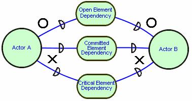
The model distinguishes three degrees of strength for the dependency according to the level of vulnerability. These types of dependencies apply independently on each side of a dependency. They are described in the following:
- Open dependency (uncommitted): Not obtaining the dependum would affect the depender to some extent but not seriously. This dependency strength is represented by including an "O" on the appropriate side of the link.
- Committed dependency: Not obtaining the dependum would cause some action for achieving a goal to fail in the depender.
- Critical dependency: Not obtaining the dependum would cause all actions to fail that the depender has planned to achieve a goal. This dependency strength is represented by including an "X" on the appropriate side of the link.
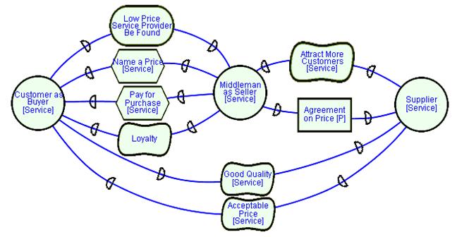
4.1.5 Strategic Dependency Example Model: Buyer Drive E-Commerce from Yu01
4.2 Strategic Rationale (SR) Model
The SR model is a graph, with several types of nodes and links that work together to provide a representational structure for expressing the rationales behind dependencies. The actors with the SD model are “opened up” to show their specific intentions. There are four types of nodes, based on the same distinctions made for dependum types in the SD model: goal, task, resource, and softgoal. There are three main classes of links internal to the i* actor: means-ends links, task decomposition links and contribution links.
SR diagrams open up Actors and show all the internal elements, including Goals, Softgoals, Tasks, and Resources that contribute to the analysis of alternatives and fulfillment of the dependencies. Goals and Softgoals can be attributed to not only human Actors, but also to non-human Actors (systems, machines, etc.) by the humans. For example, an email system (a non-human Actor) wants to be reliable, fast, and easy, because the humans who initiated these requirements or designed the system attribute these goals to the email system’s design.
4.2.1 Boundary / Actor Boundary
Actor boundaries indicate intentional boundaries of a particular actor. All of the elements within a boundary for an actor are explicitly desired by that actor. In order to achieve these elements, often an actor must depend on the intentions of other actors, represented by dependency links across actor boundaries. In turn, an actor is depended upon to satisfy certain elements, represented by a dependency link in the opposite direction.
4.2.1.1 Guideline (Beginner,Layout) Avoid or minimize overlapping boundaries of Actors where possible. Discuss
Discussion: Where possible, it is desirable to draw the boundaries of actors in a clear manner without overlapping. Overlapping boundaries and Dependency Links makes models harder to understand, interpret, and communicate. It is recommended to leave enough canvas space as much as possible between actors to allow for the Dependency Links to be drawn clearly and eligibly.
4.2.1.2 Guideline (Beginner,Layout) Keep Dependency Links outside the boundaries of Actors to improve the readability of the models. Discuss
Discussion: To make a Dependency Link clearly visible and recognizable, the Dependum as well as the “D” symbol should be drawn in space between and outside of the boundaries of Actors. Leave enough canvas space among actors to allow for the Dependency Links to be drawn clearly and legibly.
4.2.1.3 Guideline (Beginner,Layout) Use the conventional Actors’ boundaries (circles) unless other shapes such as rectangles can improve the overall layout. Discuss
Discussion: The conventional Actors’ boundaries are circles. In some instances other boundary shapes such as squares or rectangles can improve the management of the drawing space and therefore can enhance the readability and organization of the layout of the model. These non-conventional shapes, however, need to be used consistently.
4.2.2 Elements/Nodes
The meanings of these elements are the generally the same as found in dependencies, with the exception that the satisfaction of elements may be accomplished internally.
4.2.2.1 Goals (Hard Goals)
Represents and intentional desire of an actor, the specifics of how the goal is to be satisfied is not described by the goal. This can be described through task decomposition.
4.2.2.1.1 Guideline (Beginner,Concept) Use a Softgoal for quality criterion and use a (hard) goal for a sharply defined objective. Discuss
Discussion: There are goals (hard goals) and softgoals. Examples of goals are: Product Be Designed, Service Be Provided, and Team Be Hired. Examples of softgoals are: Design Process Be Efficient, Low Product Cost, and Availability Service. Not every goal is a softgoal. Use softgoals when modeling quality attributes or non-functional requirements (NFRs) or use softgoals when stakeholders’ goals are not precise or their criteria of success are not sharply defined in advance. On the other hand, a Goal is precise and its end state or outcome is clearly specified. Goals are part of the functional requirements.
As shown in the illustration, the phrase “Better service” suggests that it is likely to be a Softgoal, not a Goal. “Better service” is NOT precise, or it’s criteria of success are sharply defined in advance. “Better service” is subject to interpretation. Conversely, “Telephone Connection” is highly likely to be a Goal because the Customer is either connected or not connected. If the Customer is concerned about the Quality or Availability of the connection, then this new requirement would be modeled as a Softgoal, “Availability [Service]”.
4.2.2.1.2 Guideline (Beginner,Concept) Do not confuse Softgoal with optional, less important Goals. The criticality, or importance, or priority of a goal is orthogonal to the distinction between a hard goal and a Softgoal. Discuss
Discussion: The distinction between a (hard) Goal and a Softgoal is not in the degree of importance. To model something as a Softgoal is not to say that it is less important, or that it is optional. For example, Performance[online update] might be modeled as a critical Softgoal. In i*, dependencies may be assigned one of three levels of “strength” - Critical, Committed, or Open. The strength attribute is separate from the distinction between a Softgoal and a hard Goal
4.2.2.1.3 Guideline (Beginner,Concept) To indicate that a Goal can be achieved by performing several sub-tasks, model the decomposition by introducing a Task. Discuss
Discussion: Use a single Means-Ends Link to connect a Task to a Goal, then, decompose this Task into sub Tasks using Decomposition Links. In the example, the Task “Provide health service” is decomposed into the all the sub Tasks below it. Also, these sub Tasks can be decomposed further, if required based on the nature and context of the analysis, into more sub Goals, Softgoals, Tasks, and Resources.
Figure 1 depicts a correct scenario of a Goal decomposition by introducing a Task. Figures 2 and 3 illustrate incorrect scenarios where the main goal is incorrectly and directly decomposed using Decomposition and Contribution Links.
Note: See the guideline, “Don’t mix Goals and Tasks in the Means-Ends links” for further discussion about Goal decomposition and a note about the difference between i* and Tropos in decomposing Goals into sub-goals.
Figure 1 A correct scenario of a Goal decomposition by introducing a Task
Figure 2 A wrong scenario where the goal is incorrectly and directly decomposed using Decomposition Links
Figure 3 A wrong scenario where the goal is incorrectly and directly decomposed using Contribution Links
4.2.2.1.4 Guideline (Beginner,Concept) Use multiple Means-End Links from Tasks to a Goal to indicate alternatives. Discuss
Discussion: Using this notation gives the modeler a way to analysis the alternatives of satisfying a Goal. The impact of each alternative on
the Softgoals or NFR of the system is analyzed using Contribution Links such as: Make, Some+, Help, Break, Some-, Hurt, and Unknown.
4.2.2.1.5 Guideline (Beginner,Concept) Don’t mix Goals and Tasks in the Means-Ends links. Discuss
Discussion: Goals are different than Tasks, and therefore can’t be mixed in Means-Ends Links. A Goal is an Actor’s End desire, not a Means to achieve this End desire (Goal). In i* framework, An End desire (Goal) is achieved via a Task, which is a Means to achieve the End desire or a Goal. See Section 1.4.2.2 “Elements/Nodes” for more explanation about Goals and Tasks. Figure 1 depicts an example where the Means-Ends Links is allowed and where it is not. See the guideline in section 1.4.2.2.1 “Goal (Hard Goals)” for an example of using the Means-Ends Link and Task notations to indirectly decompose Goals to sub-goals.
Note: The i* Means-Ends Link notation is not to be confused with a similar notation used by Tropos methodology to denote an OR decomposition of Goals. Figure 2 (troposproject.org) depicts Tropos notation for both AND and OR decomposition notation. It can be noticed that Tropos allows direct decomposition of Goals to sub-goals. On the other hand, i* decomposes Goals into sub-goals indirectly using the Task notation as shown in Section 1.2 “Basic i* notation” and discussed in Section 4.2.4 “Decomposition Links”. The i* notation of Goal decomposition encourages the modeler to consider distinctions among Goals, Softgoals, Tasks, and Resources are each step of decomposition.
4.2.2.1.6 Guideline (Beginner,Naming) Use precise language to name a Goal or a Task. Discuss
Discussion: Goals have the naming convention of “Goal Be Achieved” such as: Product Be Developed, Infrastructure Be Installed, and System Be Tested. Goals should not to be confused with the Tasks, which start with verbs such as: Collect the payment, Process the request, and Test the module. Sometimes, deviation from this Goal naming convention could be allowed, however, if the naming convention seems a bit unnatural.
4.2.2.1.7 Guideline (Beginner,Concept) A Goal can only be decomposed using Means-Ends Links. Discuss
Discussion: The Means-End Link is a type of a relationship that indicates an End (Goal) and it’s Means (Task), or how to achieve the Goal. Using a Means-End Link indicates that the Means fulfills the goal. This indicates that an alternative which would satisfy the goal has been discovered. Further alternatives should often be sought. Contribution Links such as Help, Some+, etc. are used with Softgoals, not with Goals. Also, Decomposition Links are used to decompose a Task, not a Goal. Refer to Guideline 4.2.3.1 for additional discussion on using Means-Ends with Goals.
4.2.2.2 Softgoals
Softgoals are similar to (hard) goals except that the criteria for the goal’s satisfaction are not clear-cut, it is judged to be sufficiently satisfied from the point of view of the actor. The means to satisfy such goals are described via contribution links from other elements. The notion of softgoal satisfaction is described by the term satisficed meaning sufficiently satisfied. The converse is still described as denied.
4.2.2.2.1 Guideline (Beginner,Concept) Do not confuse between a Softgoal and a Task. Discuss
Discussion: Softgoals are used when modeling quality attributes or non-functional requirements (NFRs). Also Softgoals are used when
stakeholders’ goals are not precise, may change, or their criteria of success are not sharply defined in advance. Tasks are used when an actor (Depender) depends on another actor (Dependee) through the strategic Dependency Link, to accomplish a task, which has a clear idea of achieving it. The Dependee, however, still has freedom to carry out the activity within some constraints. A Task is usually is described by decomposing it into sub-elements, which could be another task, softgoal, goal, or resource. Also, Tasks don’t always have to be involved in a dependency. An actor can have internal tasks, which are not involved in a dependency.
4.2.2.2.2 Guideline (Beginner,Notation) Use the proper i* Softgoal notation. Discuss
Discussion: The graphical notation for a Softgoal in i* is the “squished” rectangle with rounded corner shape. Do not use the “cloud” shape which is used to denote a Belief in i*.
Note: The “cloud shape is used to denote a Softgoal in the NFR Framework and in Tropos.
4.2.2.2.3 Guideline (Intermediate,Concept & Evaluation) Softgoals and Goals should be decomposed. Discuss
Discussion: One of the objectives of creating i* models is to show how Goals and Softgoals can be achieved through operationalization, or though more concrete actions and design decisions included in the model. This process of finding alternatives which satisfy goals and sofgoals is called “operationalizing” or decomposing elements. Therefore, modelers are encouraged to try not to leave Softgoals and Goals as leafs elements, or elements which do not have any incoming link. Figure 1 depicts one scenario where a Softgoal is left as a leaf. Figure 2 depicts a general example of when a Softgoal is considered a leaf element or a non-leaf element. Figure 4 depicts an example of Goal leaf and non-leaf elements. In cases such as this, the model is incomplete, not all of the requirements or (soft)goals contained in the model can be achieved through the alternatives included in the model. If this Softgoal leaf element is left unconnected with other model elements through Contribution Links and/or Dependency Links, it will be difficult to know whether this Softgoal (requirement) is satisficed. It may be allowable to leave Softgoals as leafs in initial, incomplete models, but later, effort should be made to find ways to achieve all Softgoals. Figure 2 illustrates connecting such a Softgoal leaf to other model elements using incoming Contribution Link(s) or Dependency Link(s) in order to show how Softgoals are achieved.
Refining and decomposing Goals and Softgoals provide the advantage of developing more complete and accurate models. More accurate models, however, might lead to more complex models, which impacts the time, effort, and cost of the design process. Therefore, the trade-off between these different aspects should be taken into consideration. It may be advisable to leave softgoals and goals as leaf elements if the model is very large, but this incompleteness should be noted and justified.
Refer to Section 4.2.6 ‘Leaf Elements’ for definition of leaf element.
Refer to Section 4.2.8 ‘Operationalizations and Refinement of Goals and Softgoals’ for more information about refining and decomposing Goals and Softgoals.
Figure 1 One possible scenario where a Softgoal is left as a model leaf
Figure 2 Two ways to avoid leaving a Softgoal as a model leaf
Figure 3 A general example of when a Softgoal is considered a leaf element or a non-leaf element
Figure 4 Scenario where Goals are leaf and non-leaf elements
4.2.2.3 Tasks
The actor wants to accomplish some specific task, performed in a particular way. A description of the specifics of the task may be described by decomposing the task into further sub-elements.
4.2.2.3.1 Guideline (Beginner,Concept) Do not confuse between a Task and a Resource. Discuss
Discussion: In the Task Dependum, the Depender depends on the Dependee to perform a Task for which there is clear criteria of achieving the Task. A Task is an activity, which needs to be performed by the Dependee, who still has freedom to carry out the activity within some constraints. Modeling a dependency as a Task means that the Dependee must perform the Task in a particular way. On the other hand, a Resource Dependum denotes that the Depender depends on the Dependee for the availability of a resource such a physical resource or information. Modeling a dependency as a Resource means that the Depender is only interested in the availability of the resource, and does not care that the Dependee has to carry out some activity to produce it
4.2.2.4 Resources
The actor desires the provision of some entity, physical or informational. This type of elements assumes there are no open issues or questions concerning how the entity will be produced or provided.
4.2.2.4.1 Guideline (Beginner,Concept) Use a Resource when the Actor asks for the provision of a clearly defined and concrete resource, which can be physical or information entity. Discuss
Discussion: The Resource element should be clear, concrete, and well defined. Resources that are open in nature and prompts for additional actions or decisions to be made for their provision suggest using alternative elements such as Task, Goals, or Softgoals. Please refer to Section 4.1.3.3 “Resource Dependency” for discussion about the Resource entity.
4.2.2.4.2 Guideline (Beginner,Concept) Model a human or system as a resource only if you want to ignore their goals and intentions. Discuss
Discussion: An Actor is an entity that performs an activity or an action. If the Depender depends on an entity to perform a task, action, or activity to fulfill, satisfy, accomplish, or achieve a goal, then that entity is modeled as an Actor, not a Resource. In the supplied example, “Online Payment System” and “Telecom Technician” are not passive deliverables, but active elements that performs action within the overall model. Therefore, they need to be modeled as some type of actors. Moreover, the modeler decides if it is useful to model the Goals and intentions of the “Telecom technician”, for example, then it should be an Actor, otherwise, in a simple model, it could be a resource.
4.2.2.5 Beliefs
A belief is a condition about the world that the actor holds to be true. The actual degree of truth (As indicated by evaluation labels) is influenced by contributions from other beliefs. A belief is distinct from a goal in that the actor has no explicit desire to make the specified condition become true.
4.2.2.5.1 Guideline (Beginner,Concept) Describe the effect of Beliefs on Softgoals using Contribution Links. Discuss
Discussion: Please refer to section 4.2.2.5 Beliefs for definitions of the element Belief. Also, please refer to section 4.2.5 Contribution Links for definitions of various types of Contribution Links. Contribution Links can be used to describe the contribution of Beliefs on Softgoals. Also, Beliefs can receive Contribution Links from other Beliefs. Even though Beliefs can receive Contributions from other elements such as Tasks, this has not been widely used in i* models.
4.2.2.6 Guideline (Beginner,Layout) Avoid overlapping elements inside or outside Actors. Discuss
Discussion: Overlapping element within or outside Actors introduces complexity or clutter, which can worsen the readability and understandability of the model. The objective of modeling is better requirements analysis and communication. Overlapping elements make it more difficult for stakeholders to understand and use the model.
4.2.2.7 Guideline (Beginner,Layout) Connect each Strategic Dependency Link in an SR model to the correct element within the actor. Discuss
Discussion: The purpose of SR models is to show and analyze how the dependencies are satisfied between Actors. Connecting the Dependency Links their internal elements of the dependency helps in achieving the objective of SR models. In some cases, however, when the model is incomplete (in progress) and the internal element for a dependency is not known, the Dependency Link may remain connected to the Actor, as in the SD model, or remain connected to the Actor boundary. As shown in the illustration, when the internal elements of an actor are known, the Dependency Links are connected to the correct, internal elements, not to the Actor or Actor boundary. Applying this guideline helps in developing more accurate and usable models.
4.2.2.8 Guideline (Beginner,Layout) Adopt or follow a consistent direction for the goal refinement/decomposition hierarchy as much as possible. Discuss
Discussion: Adopting a consistent direction for the goal refinement and decomposition hierarchy helps in improving the overall readability, understandability, and therefore the usability of the models. Also, using such hierarchical structure allows modelers to fuse data and reduce cognitive burden on the users of the model by breaking higher level main goals into lower level sub-goals.
4.2.2.9 Guideline (Beginner,Layout) Do not draw SR model elements outside the boundaries of the corresponding actors. Discuss
Discussion: If Intentional elements, such as Goals and Softgoals of Actors are meant to by Goals and Softgoals of an Actor, they should be drawn inside the boundaries of the Actors. Intentional elements are extended between Actors only via Dependency Links. Figure 1 depicts a correct i* notation of the internal elements.
Note: In Tropos, internal elements may be shown partially attached and overlapping with an Actor. Figure 2 illustrates an example. This notation is not used in i*.


4.2.2.10 Guideline (Beginner,Layout) Unconnected elements within an Actor is indicative of an incomplete model. Discuss
Discussion: Part of the objectives of an i* SR model is to help in analyzing the fulfillment and satisfaction of intentionality elements of and Actor and in expressing the rational as related to the Strategic Dependencies between the Actors. Leaving SR elements without proper connection to related intentional elements within an actor might introduce some difficulty in the readability, understandability, and applicability of the final model.
In some other cases such as when dealing with complex models in research work, the modeler might decide to keep some elements (especially Goals and Softgoals) of an Actor without Links to other elements to indicate the presence of a Goal, for example, that has not yet been operationalized or addressed and to work as reminder so as not to forget it.
4.2.3 Means-Ends Links
These links indicate a relationship between an end, and a means for attaining it. The “means” is expressed in the form of a task, since the notion of task embodies how to do something, with the “end” is expressed as a goal. In the graphical notation, the arrowhead points from the means to the end.
4.2.3.1 Guideline (Beginner,Concept) Means-Ends are only used to link a Task to a Goal. Discuss
Discussion: The only place where a Means-Ends link can be used is between a Task and a Goal. This type of link cannot be used between Tasks, Softgoals, or between any other combinations of links. Refer to Guideline 4.2.2.1.7 for additional discussion on using Means-Ends with Goals. Figures 1 and 2 illustrate some possible scenarios of incorrect Means-Ends connections.
Figure 1 Examples of correct and some wrong Means-Ends links
Figure 2 Additional examples of wring Means-Ends links
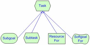
4.2.4 Decomposition Links
A task element is linked to its component nodes by decomposition links. A task can be decomposed into four types of elements: a subgoal, a subtask, a resource, and/or a softgoal - corresponding to the four types of elements. The task can be decomposed into one to many of these elements. These elements can also be part of dependency links in Strategic Dependency model(s) when the reasoning goes beyond an actor's boundary.- Task-Goal Decomposition: Subgoal. In this kind of decomposition it is not specified how the goal is to be achieved, allowing alternatives to be considered.
- Task-Task Decomposition: subtask. When a task is specified as a subcomponent of a (higher) task, this restricts the higher task to that particular course of action.
- Task-Resource Decomposition: resourceFor: The entity represented by the resource is not considered problematic by the actor. The main concern is whether it is available (and from whom, if it is an external dependency).
- Task SoftGoal Decomposition: softgoalFor: When a softgoal is a component in a task decomposition, it serves as a quality goal for that task, and thus guides (or restricts) the selection among alternatives in further decomposition of that and other tasks.
4.2.4.1 Guideline (Beginner,Concept) Be consistent with the direction of the Task Decomposition Link between a Task and sub Task or Resource. Discuss
Discussion: The direction of the Task Decomposition Link should be from the main Task to the sub Task. This type of link is used within Actors to decompose a task into sub Tasks as shown in the illustration or into other elements such as Resources, Goals, and Softgoals. Syntactically, there is nothing wrong with illustration model, but it is semantically wrong and illustrates a poor layout.
4.2.4.2 Guideline (Beginner,Concept) Be consistent with the direction of the Task Decomposition Link between a Task and a Softgoal. Discuss
Discussion: The direction of the Task Decomposition Link should be from the main Task to the Softgoal. This type of link is used within Actors to decompose a task into Softgoals as shown in the illustration or into other elements such as Tasks, Resources, and Goals. In this illustration’s particular example, the Softgoal component “Project Management Be Efficient” is a quality attribute or non-functional requirement that has been introduced for the Task “Manage Product Development Project”. This Softgoal component can be refined further into other Tasks or Softgoals, which can me be used to guide the selection among alternatives for the main Task and the sub Tasks.
4.2.4.3 Guideline (Beginner,Concept) Do not extend Decomposition Links beyond the boundaries of actors. Discuss
Discussion: Decomposition Links need to be drawn within an Actor, and not between Actors. Dependency Links should be used across Actors. These Dependency Links prompt the modeler to ask: What does Actor “Student” depend on Actor “College” for? And what is the nature of the dependency? The Answer is reflected in the Dependums, as these Dependums inform about the type of Dependency Links that are required by the modeler. Section 4.1.3 “Strategic Dependencies” discusses various types of Dependency Links that can be used between Actors.
4.2.4.4 Guideline (Beginner,Concept) Don’t use the Task Decomposition Link or Means-End Link to refine Softgoals. Discuss
Discussion: Softgoal refinement requires the use of any of the Contribution Links such as Make, Some+, Help, Break, Some-, Hurt, Unknown, And, and Or. Means-Ends and Decomposition Links can’t be used in this context.
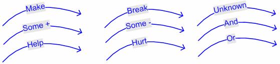
4.2.5 Contribution Links
Elements, which are discussed in Section 4.2.2 “Elements/Nodes” are: Goal, Softgoal, Task, Resource, and Belief. Contribution Links, which are also covered in this section, are: Make, Some+, Help, Break, Some-, Hurt, Unknown, And, and OR. Any of these Contribution Links can be used to link any of the elements to a Softgoal to model the way any of these Elements contributes to the satisfaction or fulfillment of the Softgoal. Goal-oriented Requirement Language (GRL) uses a variation of the i* Contribution Links notation. Refer to Guideline 4.2.5.10 for more information.4.2.5.1 Make
A positive contribution strong enough to satisfice a softgoal.
4.2.5.2 Some+
Either a make or a help contribution, a positive contribution whose strength is unknown.
4.2.5.3 Help
A partial positive contribution, not sufficient by itself to satisfice the softgoal.
4.2.5.4 Unknown
A contribution to a softgoal whose polarity is unknown.
4.2.5.5 Break
A negative contribution sufficient enough to deny a softgoal.
4.2.5.6 Some-
Either a break or a hurt contribution, a negative contribution whose strength is unknown.
4.2.5.7 Hurt
A partial negative contribution, not sufficient by itself to deny the softgoal.
4.2.5.8 Or
The parent is satisficed if any of the offspring are satisficed.
4.2.5.9 And
The parent is satisficed if all of the offspring are satisficed.
4.2.5.10 Guideline (Beginner,Concept) Use Contribution Links from any element only to a Softgoal element. Discuss
Discussion: Contribution Links are not allowed from any element to a goal, only to Softgoals. Please refer to Section 1.4.2.5 “Contribution Links” for an explanation about Contribution Links.
Figure 1 depicts only two possible cases of wrong uses of Contribution Links (from a Task to a Goal and from a Task to a Task). There are other wrong cases, however, that the Contribution Link should not be used in such as Goal to Goal, Goal to Task, Softgoal to Goal, and Softgoal to Task.
Figure 2 illustrates all the possible correct cases of using Contribution Links to a Softgoal element using i* notation.
Figure 3 depicts the GRL (Goal-oriented Requirement Language) variation of the i* Contribution Links notation.
Figure 1 An example of some possible correct and wrong uses of Contribution Links
Figure 2 Contribution Links to a Softgoal element using i* notation
Figure 3 GRL variation of the i* Contribution Links notation
4.2.5.11 Guideline (Beginner,Concept) Avoid introducing ad hoc or improvised link types. If you must, define their syntax and semantics as extensions to i*. Discuss
Discussion: Usually, Contribution Links are used to evaluate the satisfaction of Softgoals. In some instances, however, quantitative Contribution links labels (such as numbers or different symbolic types) can be used if real-life data or sources of numbers are available to evaluate contributions of alternative Tasks on the satisfaction of Softgoals. Otherwise, adding numbers is just making a finer-grained qualitative evaluation measure. The user of the model or the modeler has to be aware that it is still a qualitative measure, not to be totally trusted. Additionally, should the modeler need to introduce new link types, their syntax and semantics must be defined.
4.2.5.12 Guideline (Beginner,Concept) Use the OR Contribution Links to indicate alternatives for satisficing a Softgoal. Discuss
Discussion: The Or Contribution Link can be used, even though very rarely, to select among alternative tasks to satisfice a Softgoal. This Link means that an Actor has the choice of making a selection for satisficing the quality attribute or the non-functional requirement (Softgoal). This process of selecting among alternatives is followed by an evaluation process to make judgment on the impact of each alternative on other Softgoals in the model. Alternatively, Contribution Links such as Make, Some+, Help, Unknown, Break, Some-, and Hurt are usually used to provide a combined evidence. A choice between tasks is made by the effect of these tasks on the Softgoals itself and other Softgoals.
4.2.5.13 Guideline (Beginner,Concept) Don’t use Correlation or Contribution Links between actors. Discuss
Discussion: Dependency relationships between Actors should be represented in SD and SR models using the standard Dependency Links notation. These links should reflect all types of dependency relationships between Actors. Contribution Links (solid lines) and Correlation Links (dotted lines) should not be used between Actors. In some i* models, especially those involving security or concepts discussed in advanced research, there is a need to show attacks and defense scenarios using correlations and contributions between Actors. They add new expressive power. These correlations and contributions between Actors are treated as extensions to i*.
Examples 1 and 2 depict some exceptional scenarios where Correlation and Contribution Links (solid or dotted lines) have been used between Actors to provide more expressiveness power. It is recommended that the beginners and students do not break the general rule or the guideline of not using Correlation and Contribution Links between actors.
Additionally, Correlation Links have been used in the NFR Framework’s examples. These links basically have the same syntax as Contribution Links, from any element only to Softgoals, but drawn in dotted lines. Correlation Links represent side effects from an element (such as a Task or a Softgoal) to a Softgoal. Example 3 depicts an NFR Framework using i* notation to illustrate the concept of codification of design knowledge for reuse and building NFR catalogues. The example shows the Operationalization of a Softgoal and its correlations (side effects) on other domain related Softgoals.
4.2.5.14 Guideline (Beginner,Concept) Don’t use Correlation or Contribution Links from a Task to a Task. Discuss
Discussion: Correlation or Contribution Links are used only from any element to a Softgoal. In some instances advanced modelers might bypass this rule in Security analysis or other advanced research topics that require adding new expressive power. Therefore, it is recommended for beginners and student to follow the guideline.
4.2.6 Leaf Elements
Elements in i* SR models which are not decomposed into further elements, or Which do not receive any contribution from any link, are called leaf elements. Leaf elements can be, but are not necessarily operationalizations, as they may not represent high-level executable tasks.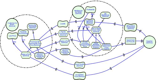
4.2.7 Strategic Rationale Example Model: Buyer Drive E-Commerce from Yu01
4.2.8 Operationalizations and Refinement of Goals and Softgoals
When softgoals are decomposed into tasks, such tasks are called operationalizations. They are achievable through a concrete action. Operationalizations can be further decomposed into further, more specific operationalizations or even to other i* elements such as goals and softgoals, necessary to achieve the tasks.Goals and Softgoals are intentional elements that could be used externally in the Dependency Links between Actors and internally within Actors. Depending on some reasons such as the required level of analysis, required efforts, complexity, and objectives of the models, internal high level Goals and Softgoals could be refined (broken down) into lower level goals and Softgoals. These refinement processes in effect, define and elaborate on the meaning of the goals and make them more concrete. Some guidelines are provided in this section to help in making the refinement process more systematic and usable.
4.2.8.1 Guideline (Beginner,Concept) Use Contribution Links to decompose or refine a broad softgoal or non-functional requirement (NFR) into smaller components. Discuss
Discussion: The decomposition and refinement of a very broad or abstract softgoal helps in making it more concrete. For example, the Security NFR is a broad quality, which can be refined, for example, into: Integrity, Confidentiality, and Availability. The And Contribution Link in this example means that all of the three components are part of the definition of the Security NFR. Advanced modelers, however, might find using the And Contribution Link restrictive because of the problem that all Softgoals must be satisficed to have any positive value for the Security NFR (in this example) and usually a modeler might want to show a partial value if only one or two of the sub-goals are satisfied. Therefore, advanced modelers might use multiple Help Contribution Links instead of the And Contribution Links. Furthermore, the type and/or topic of a Softgoal or NFR can be decomposed or refined. The guidelines and discussions for refining the type and topic of a Softgoal are discussed in the subsequent guidelines in this section.
4.2.8.2 Guideline (Beginner,Naming) To facilitate systematic refinement, use Type and Topic naming convention for Softgoals. Discuss
Discussion: It is recommended to use the Type [Topic] naming convention for Softgoals to facilitate systematic Softgoal refinement, eliminate model misunderstanding and ambiguity, maintain naming consistency within the model and among multiple models, and provide a means of promoting knowledge codification and cataloguing. In the initial stage of modeling an As-Is system, the modeler, however, may want to retain the terminology and reasoning structure of stakeholders from, for example, interview raw data. In this case the Type [Topic] naming convention may not be appropriate.
4.2.8.3 Guideline (Beginner,Naming) Where Softgoals are named according to the Type and Topic structure, be consistent in each Softgoal refinement step to refine either by Type or by Topic. Discuss
Discussion: High level Softgoals should be refined into lower level Softgoals, and eventually operationalized. The Type or Topic of a Softgoal or NFR can be refined into lower level Softgoals or NFRs. Additionally, consistent refinement of the Type or Topic of a Softgoal helps in producing consistent and systematic because it prompts modelers to consider all applicable Softgoal types for a given topic, or for a given Softgoal type, what sub-topics it is applicable to. Type [Topic] refinement process is to be done on Softgoal’s type or topic, but not both at the same time. Please refer to Chung, Nixon, Yu, and Mylopoulos (2000) for a detailed discussion about the NFR framework.
Figure 1 shows an example of refining a Softgoal using Type and Topic structure.
Figures 2 and 3 depict counter examples where the Type and Topic refinement is not consistent. For example, Figure 2 illustrates mixing or introducing a new Softgoal Type “Availability” within the refinement of the original Softgoal, “Transparency”. Figure 2 illustrates mixing or introducing a new Softgoal Topic “[Health Record]” within the Topics of the original Softgoal’s Topic “[Accounts]”.
4.3 Naming, Icons, and Colors
Labels and names are text strings that are associated with the elements of the model. They are an integral part of the standard i* notation. Non-conventional icons include such things as face and stick figures, artistic icons, and arrows. Coloring could include filling standard elements with certain colors, using specific colors to label parts or the entire model’s elements, or use colors to highlight the boundaries of Actors and their elements. Like naming and labeling, using colors and non-conventional icons sometimes can help modelers to convey certain information to the users of the model, but some of the questions that might arise are: what icons and colors should be standardized? In what context they can be used? And how to guarantee that using these non-conventional icons and additional colors are really useable by different types of stakeholders? Therefore, some general guidelines are provided in this section to help in bringing the benefit out of using names, labels, icons, and colors without jeopardizing the readability and usability of the models.4.3.1 Guideline (Beginner,Naming) Avoid including non standard elements or notations in the model. Discuss
Discussion: Non standard or conventional symbols sometimes defeat the purpose of developing a standard modeling language that can improve the consistency, usability, and reusability of the model. Different analysts may opt to use different symbols and notations to convey the same meaning. This situation creates inconsistency in reading and interpreting the model. This does not imply, however, that expanding i* notation using non-standard syntax is not allowed. New notations might add expressive power. The requirements are that the new notation needs to be clearly explained and the existing i* notation cannot be used instead.
4.3.2 Guideline (Beginner,Naming) Be consistent when using colors in the models. Discuss
Discussion: Using color in models can be useful if used properly and consistently. An accompanying Legend needs to be supplied with the model, if the analyst chooses to do so. The Legend with eliminate any confusion that might arise due to the use of these extra colors in the model. Improper use of colors in the model, however, can lead to issue of consistency and usability. Additionally, a lot of colors can be distracting.
4.3.3 Guideline (Beginner,Naming) Use a suitable font size for the element name. Discuss
Discussion: Keeping the model neat and organized helps in producing more readable and usable models.
4.3.4 Guideline (Beginner,Naming) Select concise but informative phrases to name the elements. Discuss
Discussion: Softgoal naming must be precise and conveys meaningful information. For example, a Softgoal might be labeled as: Design Process Be Efficient or alternatively, Efficient Design Process. Avoid using very vague or very abstract such as: “The process is working good”. The following illustration depicts various examples of good and bad naming for various elements.
4.3.5 Guideline (Beginner,Layout) Don’t extend the text of the name of the element beyond the element’s boarder. Discuss
Discussion: Keeping the model neat and organized helps in producing more readable and useable models.
4.3.6 Guideline (Beginner,Naming) Do not use Verbs in the names of Actors, Agents and Positions. Discuss
Discussion: Names of Actors, Agents, and Positions should not be Verbs. Avoiding using Verbs in these elements helps in eliminating readability conflict with Tasks, which are described by Verbs. Agent names can use general names such as “Employee” or specific names such “Judy”. Roles are different than Tasks. Tasks are used when an actor (Depender) depends on another actor (Dependee) through the strategic Dependency Link, to accomplish a task, which has a clear idea of achieving it. The Dependee, however, still has freedom to carry out the activity within some constraints. A Task is usually is described by decomposing it into sub-elements, which could be another task, softgoal, goal, or resource. Also, Tasks don’t always have to be involved in a dependency. An actor can have internal tasks, which are not involved in a dependency. In contrast, a Role is not a Task but an abstract characterization, which is played by an Agent or Covered by a Position. Also, A Role is specific type of an Actor, which can contain its own elements such Goals, Softgoals, Tasks, and Resources. Therefore, it should not be confused with Tasks, which are just one possible element of a Role. Also, not only human Actors can play Roles, but also nun-humans (such as systems) can play Roles.
4.3.7 Guideline (Beginner,Naming) Use clear names without ambiguous and unknown abbreviations or acronyms. Discuss
Discussion: Names of Actors, Agents, Roles, and Positions should be clear. Ambiguous abbreviations might make it harder for some of the stakeholders to read, interpret, and understand the model. Therefore, abbreviations are not recommended unless a legend is supplied to explain their meaning.
4.4 Scaling
Models could grow in terms of the number of Actors of a model, number of external and internal elements that are associated with these Actors, the level of the refinement and decomposition of these elements, and the depth of the concepts that represent the domain of the system that is being modeled. When models grow and become more complex, scalability issues may arise. Therefore, using some guidelines that deal with these issues could help in suggesting ways of presenting complex models to the users of the models in a readable, easy to use, and usable manner. This section provides some guidelines on scaling and complexity issues.4.4.1 Guideline (Intermediate,Layout) Split a large and complex model into consistent pieces to facilitate easier presentation and rendering. Discuss
Discussion: Large models may be split into consistent pieces to facilitate easier presentation and rendering. In such instance, the model’s pieces need to be consistent with each other. Each piece is just a view or subset of a larger conceptual model, even if a physical representation of this model doesn’t exist due to space constraints. As shown in the illustrations extracted from Horkoff, Yu, and Liu (2006), Figures 2 to 4 are pieces or segments of the complete SD and SR diagrams in Figures 1 and 5. The objective of presenting this example here is not to go through the internal logic or content of the case, but to illustrate the overall layout and arrangement of consistent pieces or segments of complete SR and SR models. Please refer to “Trusted Computing: An i* Case Study” by Horkoff, Yu, and Liu (2006) for full details about this case.
4.4.2 Guideline (Intermediate,Layout) Don't extract or zoom into a section of an Actor in a model without showing the incoming and outgoing dependencies with other Actors or parts of the model. Discuss
Discussion: Zooming into or extracting a section of a model is one way to facilitate working and analyzing sections or parts of a large or complex model. Zooming, however, need to be dealt with cautiously. All the related incoming and outgoing links of the zoomed section need to be shown. Neglecting or missing some of the links leads to inconsistent model, which can be hard to read, interpret, understand, and communicate.
4.5 Level of complexity
4.5.1 Agents, Roles, and Positions
4.5.1.1 Guideline (Intermediate,Layout) Use the specialized actor notation to the degree that you can gain advantage and higher level detailing in instantiating the actual stakeholders. Discuss
Discussion: It has been outlined in Section 1.3.1.1 “Actors” the guideline of using Agents and Roles instead of the general Actor notation when the distinction is easily made. Choosing to use the specialized Actor notations such as Agent, Roles, and Positions can help in gaining higher level of detailing in instantiating the actual stakeholders and capturing the knowledge domain. On the one hand, lack of use of any of these specialized actor notations might subject the model to some lose of useful information. On the pother hand, excessive use of the special actor notations might lead to much more complex models that might become harder to deal with. Therefore, it is recommended to subject the choice for the use of the general Actor versus the specialized Actor notation based on the value and additional information that they will add to the model.
4.6 Model Analysis
The i* Framework provides concepts which facilitate the analysis of the success of domain situations represented in models.4.6.1 Ability
When an agent has a routine that can serve some purpose, e.g., to achieve a goal, we say that the agent has an ability to achieve that goal. In this formulation, an actor has the ability to do something if it has a routine for it. Having ability does not necessarily imply that one can achieve something all by oneself. Various degrees of delegation and external dependency may be involved.4.6.2 Workability
The notion of “workability” indicates that an agent believes that some routine would work (at run-time) even though it is incompletely specified or known. Thus, the actor is confident that, at execution time, it will be able to carry out the reasoning and actions required to achieve the result. A routine is judged to be workable if each of its explicitly mentioned elements is workable, and if all the constraints in the routine are expected to hold. Thus, an element is made workable by reducing it thought the routine to primitively workable elements (though not necessarily primitively executable actions), or by delegation some of the elements to other agents. A primitively workable element is one that is judged to be workable without further reduction. At an actor boundary, an open element is workable if there is some actor offering this element. A committed element is workable if there is another actor committed to producing this element as dependum to the first actor.4.6.3 Viability
The notion of “viability” indicates what the level of evidence that indicates that the routine will work. We say that a routine is viable if all its softgoals are satisfied. Softgoals at the top level are selectively applicable to elements at lower levels in the functional means-ends hierarchy, as selected by the means-ends hierarchy of softgoals, via the parameters in the softgoal nodes.4.6.4 Believability
Since the SR model relies on judgment and argumentation, there are many assumptions made as the model is constructed. A fourth level of assessment is in the believability of these assumptions. A qualitative treatment of these is also assumed.4.6.5 Evaluation and Propagation
This section discusses the main concepts, notation, and qualitative process or procedure of using i* models for evaluation. General recommendations and guidelines, associated with discussions and illustrations, are provided as well. It is intended in this i* Guide to present the fundamental concepts and the process in a simple and easy to understand manner. Is it a good staring point to explore i* evaluation. The intent of this section is to bring about some of the necessary elements (such as propagation rules) of conducting a sound analysis to arrive at reasonable answers to the analysis questions. For additional discussions on using i* models for evaluation, including topics of Evaluation script and algorithm, convergence, termination, human judgment, and giving labels to non-leaf elements, we would like to refer you to the original references upon which the content of this section has been based. These references are: Horkoff (2006), Horkoff (2004), Horkoff and Yu (2005), Horkoff, Yu, and Liu (2004), Horkoff, Yu, and Liu (200), and Horkoff and Yu (2005). Please refer to the reference section at the end of the Guide for full citations of these resources. Also, the example that is used in Evaluation Step 2 in Section 4.6.5.1.5.2 does not depict the underlying algorithm for the Evaluation procedure step-by-step, but combines simpler steps together to give more condensed exampleThis i* Guide has provided in various sections some recommendations on the use of i* notation for developing consistent, readable, understandable, and usable SD and SR models. Also, SR models and their associated elements have been discussed in section 4.2 “Strategic Rational (SR) Model”. An SR model is the place where the modeler works within Actors to model their internal elements and model the way these elements are thought to contribute to the satisfaction and fulfillment of Actor’s internal goals and other Actors’ dependencies via the Dependency links.
Now, the question is how can the modeler tell whether the model and its web of internal elements really fulfilled and satisfied Actors’ goals and dependencies? What options are available? Or what is the effect of one element on other elements? The answers to these questions touch the very essence of i* modeling framework, which uncovers the reasoning and rational behind making informed modeling decisions through using i* models for evaluation. Also, i* evaluation is believed to have another important advantage of enhancing the overall quality (accuracy and comprehensibility) of i* models by prompting the modeler for change as a result of verifying the syntax and validating the meaning of the models.
As we will see in this section, human intervention or judgment arises as a useful or maybe even a necessary strategy in the evaluation process, especially when modeling the complex interactions of an organizational network. Therefore, because it is infeasible to create a model which captures the complex interactions completely, informed and careful human intervention in the evaluation process is allowed to compensate for some issues related to lack of information or model precision, correctness, and completeness. The “Propagate Label Values” step of the evaluation process presented below provides additional discussion about this topic.
4.6.5.1 Evaluation Procedure
The following is the qualitative procedure that is recommended to be followed to conduct an evaluation using i* models. To illustrate the procedure in a practical way, a series of simple models, which are extracted from Horkoff (2006) is provided. To facilitate the understandability and comprehensibility of the procedure, each model is associated with a discussion that points to the evaluation step and label propagation rule being used. The referenced rules are provided only as guidelines that can be adapted by intermediate and advanced users as appropriate in more advanced situations. The ultimate objective of this section is to provide the modeler with a method that can help in producing understandable, comprehensible, and transferable models. One way to achieve this objective is by utilizing the recommend steps to systematically develop models that are characterized by more explicit facts than tacit knowledge in the minds of the modelers and evaluators. The following sub-sections discuss in detail all what the evaluator needs to get started.
Evaluation procedure or process consists of several steps, which are listed below. Each step is discussed in sufficient detail in the subsequent sub-sections to get started with the procedure.
• Step 1 Decide what analysis question you are asking the model
• Step 2 Give initial Labels to “leaf nodes or elements” based on the question that you have decided to apply in Step 1
• Step 3 Propagate Label values
• Step 4 Interpret the results
• Step 5 Repeat steps 1 to 4 for each analysis question
4.6.5.1.1 Guideline (Intermediate,Evaluation) To achieve more reliable and accurate evaluation results, employ a systematic evaluation procedure instead of using a manual mental method to guess the answer for an analysis question. Discuss
Discussion: The modeler might attempt to use a mental or manual method of guessing the answer for an analysis question by tracing through the links without going through the systematic evaluation procedure that we are discussing in this section. While this method can produce some analysis results for relatively simple models, it is highly likely that evaluating more complex models can produce analysis results that are difficult to acquire by manually examining the model. Therefore, the benefits of obtaining more accurate and reliable analysis results justify and pays off spending the required time to evaluate i* models.
4.6.5.1.2 Guideline (Intermediate,Evaluation) In order to fully account the effects of all elements in the model, follow the evaluation procedure and steps in order. Discuss
Discussion: The evaluation procedure discussed in this section provides the modeler with a step by step and systematic approach to the logic and rational behind the evaluation process. The intent of this procedure is to bring about some of the necessary elements (such as propagation rules) of conducting a sound analysis to arrive at reasonable answers to the analysis questions. See Horkoff (2006) for a fuller and more advanced and detailed discussion, including Evaluation script and algorithm, convergence, termination, human judgment, and giving labels to non-leaf elements.
4.6.5.1.3 Evaluation Step 1: decide what analysis question you are asking the model
This is the first step, or you may call it the pre-requisite step for the first step, of the evaluation process. At this point, the modeler poses a question for the model to answer. Multiple questions could be formulated to explore and compare various “what-if” scenarios. Also, one “what-if” question may involve multiple parts so the modeler can test the effects of more than one element on more than one element.
Figure 2 in the next section 4.6.5.1.4 depicts one model out of a series of relatively simple models that are created to illustrate the evaluation procedure. At this stage, we would like to pose an analysis question to the model and try to use the model to answer this question.
The question that we would like to explore is: If the PC product Provider (Role) decides to not Allow Peer-to-Peer Technology (Softgoal), what effect will this have on Sell PC Products for Profit (Task)? The next steps of the evaluation procedure walk through the model to answer this question.
Other questions could be asked. For example: if the PC Product Provider (Role) decides to Allow Peer-to-Peer Technology (Softgoal), what effect will this have on Affordable Pc Product (Softgoal) of the PC User (Role)? Also, if the PC User (Role) decides to Obtain PC Products from Data Pirates (task), what effect will this have on the Profit (Softgoal) of the PC Product Provider (Role)?
The Modeler might answer a question about elements that have simple and noticeable interactions. Generally, an answer to a question tends to be harder when the relationship between the nodes must be traced though the model.
4.6.5.1.3.1 Guideline (Intermediate,Evaluation) Formulate an analysis question before giving initial labels to leaf nodes or elements. Discuss
Discussion: Step 1 of the Evaluation procedure is a significant step because it orients the modeler to give the initial evaluation labels as discussed in the Steps 2 of the Evaluation procedure. Overlooking this step and jumping to the next one is analogous to inquiring a search engine without supplying the search criteria.
4.6.5.1.4 Evaluation Step 2: Give initial Labels to “leaf nodes or elements” based on the question that you have decided to apply in Step 1.
Leaf elements are the starting points in the evaluation. They are not decomposed into further elements and have no input links because they are the lowest level in the refinement or decomposition hierarchy within Actors. In i*, leaf elements could be soft elements such as Softgoals, or hard elements such as Goals, Tasks, and Resources. The possible initial label values that can be assigned to leaf elements are illustrated in Figure 2. As depicted in the Figure 2, values range from the lowest or minimum (Denied) to the highest or maximum (Satisfied) with partial and other values in between.
These labels represent qualitative judgment of the level of the elements’ satisfaction or denial. Table 1 provides explanations of these labels:
Section 4.2.2 “Element/Nodes” explains the meaning of and the difference between i* elements.
Please refer to section 4.2.5 “Contribution Links” for discussions about various types of Contribution Links. Table 2 provides explanations of various Contribution Link Types:
For example, Figure 2 depicts an illustration of giving initial labels that correspond to the analysis question to two leaf elements, which are circled in red. We marked the Allow Peer-to-Peer Technology (Softgoal) as Denied and marked Produce PC Products (Task) as Satisfied to get started with answering the question stated earlier.
You can also see in Figure 2 the labels of the Contribution Links, which were used as an integral part of developing the SR model itself. We can see, for example, Purchase PC Product (task) in PC User (Role) has two Contribution Links: The Make Contribution Link to Abide By Licensing Regulations (Softgoal) and the Hurt Contribution Link to Affordable PC Products (Softgoal). You can also see other Contribution Links used in this sample model in both PC User and PC Product Provider Roles. There are no Contribution Links that are used or shown in Data Pirate (Role) in this simplified illustration.
4.6.5.1.4.1 Guideline (Intermediate,Evaluation) Give initial labels to the leaf elements in a consistent manner with the analysis question or scenario. Discuss
Discussion: The purpose of labeling or highlighting the leaf elements is to mark those elements that correspond to the analysis question and work as a guide to the starting point from where the evaluation and propagation starts. So, this labeling activity makes it easier for the readers of the model to understand what initial leaf elements were considered for answering the analysis question. Let us look at the example in the following model. Suppose the analysis question is: “If PC Products which meet the PC Product Provider's standards for Compatibility, Security, Freedom of Use and Affordability are produced, are the main elements of the PC User and PC Product Provider satisfied?” The illustration depicts a correct set of initial labels for the leaf elements (thin red circles) that correspond to the analysis question and an incorrect set of labels ( thick blue circles).
It is also often necessary to give initial labels to leaf elements that are not necessarily directly related in the analysis question in order to have a propagation that that makes sense. In Figure 2 presented in Evaluation Step 2, Produce PC Products is an example. The molder doesn’t really care that much if actors produce products, it’s just a necessary leaf node that needs to be given a value in order to see the results of not allowing peer to peer technology.
4.6.5.1.5 Evaluation Step 3: Propagate Label Values
The next step in the qualitative evaluation procedure is to propagate the labels that are given by the modeler to the leaf elements to other nodes. Label propagation is based on a set of propagation rules, used with human judgment, to determine the resulting label.
The following sub-sections discuss label propagation rules, the underlying algorithm, and give an example of applying these propagation rules. The propagation rules are provided only as guidelines, which can be adapted by intermediate and advanced users as appropriate in more advanced situations.
4.6.5.1.5.1 Label Propagation Rules
Label propagation rules that deal with Dependency Links, Contribution Links, Decomposition Links, and Means-Ends Links are classified and summarized in the following list of 10 rules:
Dependency Links related rules:
1. A Dependum acquires the value of the Dependee.
2. The Dependers take on the value of the Dependum.
Decomposition Links related rules:
3. The Decomposition Link relationship is treated as an “and” in the evaluation process and therefore all of the decomposed elements must be satisfied in order for the upper level task to be satisficed. With the “and” logic, the upper level task acquires the minimum value given or marked to lower level elements. Please refer to Figure 1 in Evaluation Step 2 above for the possible labels values.
4. If a node is involved in decomposition as well as a dependency, the values produced by these two relationships are resolved using “and” logic and therefore the node acquires the minimum or lowest value.
Means-Ends related rules:
5. The means-ends relationship is evaluated using “or” logic between the means. With the “or” logic, the Ends take on the maximum value given or marked to the Means.
Contribution Links related rules:
6. The upper Softgoal that has multiple “And Contribution Links” takes on the minimum label of the contributing nodes or elements
7. The upper Softgoal that has multiple “Or Contribution Links” takes on the maximum label of the contributing nodes or elements
8. Use the rules in Table 3 to propagate the labels of multiple Contribution Links (Make, Help, Some+, Break, Hurt, Some-, and Unknown) from the lower contributing elements to the upper Softgoal.
9. In cases when there is only one label, or when combining full and partial value or evidence, the final label for an element can be determined automatically. For example: the final label of an element receiving a bag of labels {Partially Satisfied, Satisfied} can be set automatically to Partially Satisfied. Table 4 lists the cases that can be resolved automatically.
10. Use human judgment when dealing with a Softgoal that receives multiple labels which cannot be resolved in automatic cases. For instance, when an element receives both positive and negative values or evidence, such as {Partially Satisfied, Partially Denied}, or when multiple sources of only positive or only negative partial values or evidence is present, such as {Partially Denied, Partially Denied} and {Partially Satisfied, Partially Satisfied}, the evaluator can decide if this evidence is strong enough to satisfice or deny an element, fully or partially, or whether to the evidence is conflicting, combining the evidence to produce one of the evaluation labels.
4.6.5.1.5.2 Step By Step Label Propagation Rules Example
Now, we would like to do some practice and continue discussing the model that we have introduced in Figure 2 in Evaluation Step 2 above to demonstrate how these propagation rules are actually applied via a series of models that are depicted in Figures 3 to 9 below. In Figure 2 , two initial labels were given. Please refer to this figure again to have another look at these two initial labels before proceeding to the following figures outlining a step-by-step example for label propagation rules.
Also, the description associated with this example does not depict the underlying algorithm for the Evaluation procedure step-by-step, but combines simpler steps together to give more condensed example.
Figure 3 depicts the elements that are receiving new evaluation labels (circled in red) in this stage of the propagation process. Here is the explanation for each circle:
- Following Rule# 1, the Resource Dependum, PC Products, acquires the value of the Task, Produce PC Products, in the Dependee
- Following Rule# 1, the Softgoal Dependum, Allow Peer-to-Peer Technology, acquires the value of the Softgoal element, Allow-Peer-to-Peer Technology.
- Following Rule# 2, the Task element, Make Content Available Peer-to-Peer, in the Depender takes on the value of the Softgoal Dependum, Allow-Peer-to-Peer technology.
- Applying the 6th line in the table in Rule# 8, the Softgoal element, Desirable PC Product, receives the Partially Denied label from the Help Contribution Link

Figure 4 depicts the next illustration of the propagation. Please follow the elements circled in red. Here is the explanation for each circle:
- Applying the 5th line in the table in Rule# 8, the Softgoal element, Profit, receives the Partially Denied label from the Help Contribution Link. Notice that this Softgoal is involved in another Contribution Link which does not have a label yet.
- Following Rule# 1, the Resource Dependum, Pirated PC Products, acquires the value of the Task, Make Content Available Peer-to-Peer, in the Dependee
- Following Rule# 2, the Task element, Obtain PC Products from Data Pirate, in the Depender takes on the value of the Task Dependum, Pirated PC Products.
Figure 5 depicts the next illustration of the propagation. Please follow the elements circled in red. Here is the explanation for each circle:
- Following Rule# 2, the Task element, Purchase PC Products, in the Depender takes on the value of the Task Dependum, PC Products.
Figure 6 depicts the next illustration of the propagation. Please follow the elements circled in red. Here is the explanation for each circle:
- Following Rule# 5, the Goal element, PC Products Be Obtained, in the Depender takes on the maximum value of the two contributing tasks using the “or” logic.
- Following Rule# 3, the Task element, Sell PC Products for Profit, in PC Products Provider, takes on the minimum value of the decomposed elements using the “and” logic.
- Notice that the Softgoal element, Abide by Licensing Regulations, in PC User receives multiple Contribution Links from the two Tasks. Applying the first and sixth lines in the table of Rule# 8, we get a bag of multiple values: Satisficed and Partially Satisficed values. This bag is then resolved using Rule# 9 by giving the Softgoal the value or label of Satisficed.
- Notice also that the Softgoal element, Affordable PC Products, in PC User receives multiple Contribution Links from the two Tasks. Applying the first and sixth lines in the table of Rule# 8, we get a bag of multiple values: Partially Denied and another Partially Denied. This is an example of a situation where human judgment is needed. Following Rule# 10, this bag is resolved into a Denied label because the evaluator judges and decides here that there is a strong evidence to deny the Softgoal.
Figure 7 depicts the next illustration of the propagation. Please follow the elements circled in red. Here is the explanation for each circle:
- Following Rule#1, the Softgoal Dependum acquires the value of the Softgoal in the Dependee.
- Following Rule#2, The Softgoal element, PC Users Abide By Licensing Regulations, in the Depender, takes on the value of the Softgoal Dependum.
Figure 8 depicts the next illustration of the propagation. Please follow the elements circled in red. Here is the explanation for each circle:
- Notice that the Softgoal, Profit, is given the Conflict label. In Figure 5 this label was Partially Denied. Why is this happening? As you can see, the Profit Softgoal now has a bag of two labels from tow Contribution links. Applying the first and fifth lines of the table in Rule# 8, we get a bag of Partially Denied and Partially Satisficed. This situation is one of those that require human judgment and decision about the final label to be given to the element. The evaluator can decide that the overall evidence of the element is either positive or negative, or can decide that the evidence is of comparable strength, and give the Softgoal a Conflict evaluation label. In this example, the evaluator judged the situation and decided to give the Conflict label.
Figure 9 depicts the next illustration of the propagation. Please follow the elements circled in red. Here is the explanation for each circle:
- In this last illustration, and following Rule# 3, the “or” logic used to resolve the labels of the Decomposition Links by acquiring the minimum value. The Task element, Sell PC Products For Profit receives the Conflict propagation label.
4.6.5.1.5.3 Guideline (Intermediate,Evaluation) Contributions from multiple elements typically require human judgment. Discuss
Discussion: There are situations in which propagation rules follow an automatic and straight forward propagation. It has been observed, however, that in reality there are many other situations involving Contribution Links that are more complex than those suggested by the propagation rules presented in this section. In such complex situations, a soft element might receive multiple, contradictory and conflicting Contribution Links from the lower elements. In similar instances, when a soft element receives both positive and negative values (evidence), or when there is no source of sufficient evidence from lower elements, human judgment or intervention is needed to decide what label to give to the soft element. Human judgment needs to be educated and supported with utilizing the semantic meaning and the underlying contextual and domain knowledge of the elements. Figure 5 in the step by step example illustrates similar instance..
4.6.5.1.6 Evaluation Step 4: Interpret the Results
Once the label values of the Contribution Links and the labels that were initially given to leaf elements were propagated through the model, the modeler is now ready to interpret the answer for the analysis question posed at the beginning of the qualitative evaluation procedure.
Now, in order to complete our demonstration of the ability of i* evaluation to facilitate analysis by providing answers to strategic questions, we would like to discuss the interpretation of the question that we have posed in Step 1, which is: If the PC product Provider (Role) decides to not Allow Peer-to-peer Technology (Softgoal), what effect will this have on Sell PC Products for Profit (Task)?
Please refer to Figure 9 as the reference for the following analysis. We can reason that as the PC User is not able to Obtain PC Products from the Data Pirate, in order for PC Products to Be Obtained, the PC User must Purchase PC Products. Even though this reasoning at the surface might lead to the conclusion that this situation has a positive effect on Profit, the final analysis result shows a conflict for Profit as a result of the Desirable PC Products Softgoal.
The overall result is a Conflict value for the Sell PC Products for Profit Task. The modeler of the example concluded that preventing the use of peer-to-peer technology will reduce piracy, but will also make products less desirable to users; therefore the overall effect on business profit for PC product providers is Conflict or both positive and negative.
4.6.5.1.7 Step 5: Repeat steps 1 to 4 for each analysis question
Once the interpretation of the results is completed, steps 1 to 4 can be repeated again to explore another analysis question with a new set of initial labels. By making multiple evaluations, the modeler can investigate several “what-if” scenarios and make informed comparisons for the strategic questions under consideration. Like with any other analytical method, as the modeler becomes familiar with the evaluation procedure, the average time and effort required to conduct future evaluations decreases and the benefit and return on investment increases and become more concrete and apparent.
Also, the level of the effort and time required to conduct an evaluation depends on the tool used in the analysis. For example, propagation process is done completely manually using istar_stencil in Microsoft Vision and done semi-automatically using OM3 tool. Semi-automatic because it allows for human judgment and intervention as discussed in the evaluation Step 3 above. Please refer to i* Wiki Website to review a variety of software tools that are available to i* modelers.
4.7 Methodology
4.7.1 Early and Late Requirements
The i* modeling framework provides the modeler with a tools-supported graphical notation that facilitates the ability to make informed choices on what procedure to follow during the modeling process. The set of guidelines discussed in this section intends to provide the beginner modeler with methodologies, or procedural choices, or approaches that can help in attaining systematic modeling processes and drawing a clear line between the As-Is situation, which captures what exists now versus the To-Be situation, which models what might exist in the future. Both AS-Is and To-Be models deal with early requirements. The To-Be model(s) can be later further decomposed to produce more detailed, later requirements.4.7.1.1 Guideline (Beginner,Methodology) Model the As-Is state of the knowledge domain and the current system status (if exists) without the presence of the new system To-Be introduced. Discuss
Discussion: At this initial modeling stage, the goal of the model is to capture the As-Is situation and reflect the state of the world under analysis. The model here deals with the related stakeholders and models the current system as an actor(s) if it exists. The benefit of doing this type of analysis is to analyze why the As-Is system fails to meet the stated requirements of the stakeholders, and to form a basis for the evaluation of new system alternatives. Also, the modeler needs to state in the caption whether the model is As-Is or To-Be.
4.7.1.2 Guideline (Beginner,Methodology) Model the To-Be state of the knowledge domain under analysis including the new To-Be system. Discuss
Discussion: This is a more elaborate stage where the To-Be system is introduced as a new actor(s). Analyze actors, agents, roles, and positions in association with the new To-Be system to make decisions about what parts, functionalities, and requirements of the To-Be system will be done by whom and what parts of the new system. The intentional and goal-oriented capabilities, guided by the non-functional requirements, help in making decisions, which are grounded on informed and systematic rational. This can add more complexity to the As-Is model, which is used to analyze alternatives and make system design decisions.
4.7.1.3 Guideline (Beginner,Methodology) Start the modeling with the SD model to capture the stakeholders and their associated strategic Dependency dependencies and interactions. Discuss
Discussion: Start with this level of complexity to discover if other stakeholders have been neglected, understand the domain under analysis, and uncover any issues related to the analysis and design alternatives. SD models are relatively less complex than SR models. Therefore, this guideline could be optional and useful for students and beginners. Advanced users, however, might start with an SR model first then collapse the actors to form an SD model. Not all i* notation tools, however, can facilitate automatic collapsing for the Actors.
4.7.1.4 Guideline (Beginner,Methodology) Employ SR models to expand on the SD models and add the intentionality and rational dimension to the analysis. Discuss
Discussion: In case you start with and SD model to explore the various Actors in the domain under analysis, open up the Actors and systematically add new dimensions about the internal intentionality of the Actors to develop SR models that can be successfully used to uncover the rational behind the satisfaction or denial of the internal elements and external dependencies.
4.7.2 Progressive Elaboration
4.7.2.1 Guideline (Beginner,Methodology) Start an SD model with the actors involved, then add Dependency Links starting with Resources, then Tasks, then Goals, then Softgoals. Discuss
Discussion: Progressive elaboration guideline is a methodology that helps the beginner modeler to keep creating, modifying, and building upon the basic model, in an organized way to achieve the goals of the modeler. It makes SD/SR modeling more systematic as models evolve. While this guideline might be useful for students or beginner modelers, it might not be necessarily true for advanced users in all scenarios. The objective of presenting this example here is not to go through the internal logic or content of the case, but to illustrate an example of progressive elaboration. Please refer to “Montreux Jazz Festival i* Exercise on based on Osterwalder Ph.D. Thesis presentation” by Horkoff (2004) for more details about this case.
4.7.3 Guideline (Beginner,Methodology & Layout) Use the leaf-level tasks as the system requirements, not the high level functional goals and non-functional softgoals. Discuss
Discussion: High level functional goals need to be refined and non-functional softgoals need to be refined and operationalized. The Main tasks that are connected to the goals using Means-Ends Links need to be refined to lower level tasks. As well, the refined softgoals need to be operationalized to lower level tasks. All these lower level (leaf) tasks constitute the actual system requirements. The level and depth of the refinement, however, depend on some factors such as, the efforts that need to be spent in modeling, the scalability of the model, and the purpose of the model. Therefore, the modeler might try to acquire low-level requirements, or sometimes only assess high-levels options.
5 Acknowledgments
The i* Guide owes almost everything to the numerous people who took the time to help in the preparation, review, and publishing of the Guide. Prof. Eric Yu and Jennifer Horkoff provided very helpful and critical feedback and guidance on both the content and organization of the Guide. The Guide would not have been possible without their continuous review, motivation, and encouragement.Special thanks also go to Dominik Schmitz for his time, proactive and relentless efforts, and invaluable technical advice and assistance for publishing the Guide on i* wiki. I am also grateful to Gemma Grau for her thoughtful suggestions and ideas to improve the usability and benefit of the Guide to i* users. Thanks also to Reza Manbachi and all the anonymous individuals who thankfully contributed to publishing the Guide.
6 References
Horkoff, J. (2006). Using i* modeling for evaluation, Master Thesis, University of Toronto, Department of Computer Science. Retrieved on July 27, 2007 from http://www.cs.utoronto.ca/~jenhork/MScThesis/Thesis.pdf.Horkoff, J. (2004). T Montreux Jazz Festival i* Exercise presentation. Based on Osterwalder Ph.D. Thesis.
Horkoff, J., Yu, E., & Liu, L. (2006). Analyzing Trust in Technology Strategies presentation. Privacy, Security, Trust 2006. Markham, Ontario, Canada. October 31, 2006October 2006.
Horkoff, J. and Yu, E. (2005). Using the i* Evaluation Procedure for Model Analysis and Quality Improvement presentation. Second International Workshop on i* / Tropos. University College London, London UK.
Horkoff, J., Yu, E., & Liu, L. (2004). Trusted Computing: An i* Case Study presentation. Department of Computer Science. University of Toronto.
[NFRbook] L. Chung, B.A. Nixon, E. Yu, J. Mylopoulos. Non-Functional Requirements in Software Engineering (Monograph)
Kluwer Academic Publishers, 2000. 472 pp.
[PST06] J. Horkoff, E. Yu, L. Liu. (2006). Analyzing Trust in Technology Strategies. . Int. Conf. on Privacy, Security, and Trust (PST'06), Toronto, Canada, Oct 30— Nov 1, 2006.
[SREIS02-Sec] L. Liu, E. Yu, J. Mylopoulos. Analyzing Security Requirements as Relationships Among Strategic Actors. 2nd Symposium on Requirements Engineering for Information Security (SREIS’02). Raleigh, North Carolina, October 16, 2002
Yu. E. (2006). Computer Science Department. University of Toronto. Prof. Eric Yu Website. Retrieved on July 28, 2007 from http://www.cs.toronto.edu/%7Eeric/#Research%20Interests.
[Yu01] Yu, Eric. Presentation: Strategic Actor Relationships Modelling with i*, December 13-14, 2001, IRST, Trento, Italy.
[Yu95] E. Yu. Modelling Strategic Relationships for Process Reengineering Ph.D. Thesis. Dept. of Computer Science, University of Toronto. 1995.
The evolution of i* syntax, deviating from the original description in [Yu95] has occurred over the course of many papers. Such work can be found in the i* Roadmap.